A Thermowell Calculation mistake everyone makes
While performing complex engineering calculation we lose sight of simple laws of physics.
For instance velocity of fluid in pipe is inversely proportional to the area of pipe.
Do you remember while watering plants, we partially block the hole of pipe to have high velocity of water being sprayed on plants.
It’s a simple phenomenon of physics that as soon as we restrict the area of flow the velocity increases.
We know that for wake frequency calculation one of the most important parameter is velocity of fluid.
Now let’s consider two practical scenarios where the thermowell is under-designed or over-designed due to incorrect velocity considerations.
Case 1: Thermowell is over-designed
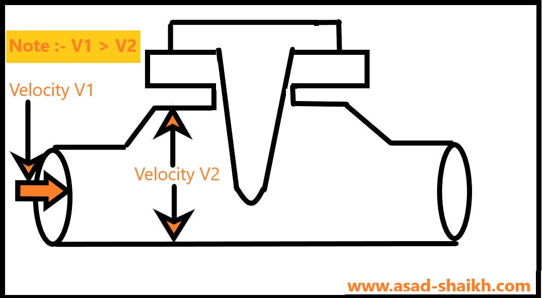
This happens for especially shorter lines.
As a rule of thumb it is recommended to swage up lines up to 4 inches for smaller line sizes like 1&1/2 inches or 2 inch line sizes.
Thus when swage up the line to 4 inches or swage up line as per client preference we might lose sight of the fact that the velocity would also change.
It has a high probability that such small line size would have a very high velocity profile for the fluid, thus our thermowell would fail the wake frequency calculation.
However after the line is swaged to 4” the velocity would drastically reduce and there is a high chance that our thermowell will easily pass the wake frequency calculation test.
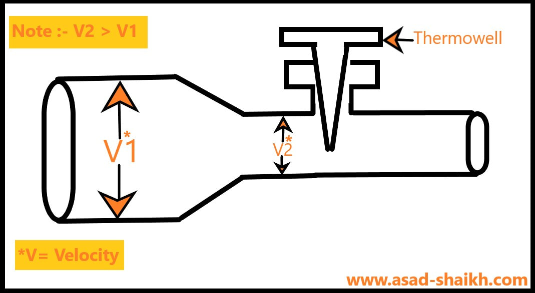
Case 2: Thermowell is Under-designed
Imagine a situation highlighted below where the thermowell is mounted on line that has employed a reducer to lower the line size.
Here there is a safety concern and requires special confirmation from process engineer whether the velocity provided is of the higher line size or that of the reduced line size since these velocities would be different.
Note that the velocity value in the reduced line size will be higher than that of the original larger pipe
Solutions:
1. The first obvious solution seems to verify velocity values with the process engineer when such cases arise.
2. The second solution is to get a flow rate from process engineer and calculate the velocity ourselves.
Here is a simple way to do it
Q(Vol.Flow) = V1 (Velocity) X A1 (Area)
Thus
Velocity = Volumetric flow rate / Area
The following diagram explains this concept in pictorial form.
2. The second solution is to get a flow rate from process engineer and calculate the velocity ourselves.
Here is a simple way to do it
Q(Vol.Flow) = V1 (Velocity) X A1 (Area)
Thus
Velocity = Volumetric flow rate / Area
The following diagram explains this concept in pictorial form.
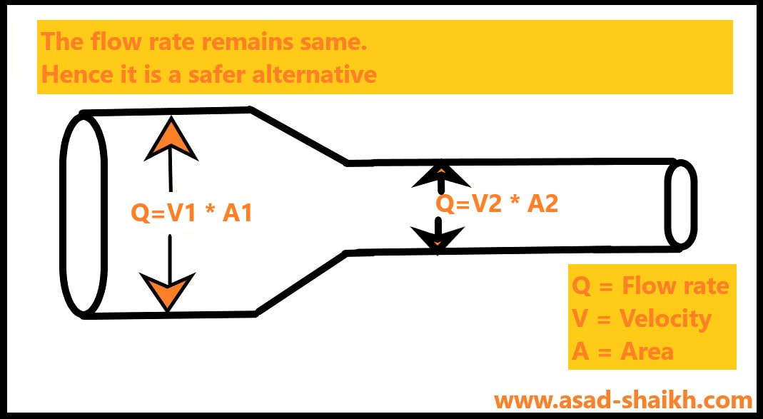
We know the Flow (Input from process engineer) and the Area (area of pipe is already known) and Hence Velocity can be easily calculated.
Hope you have found this article helpful.
Hope you have found this article helpful.
A small gift
After spending a year on studying diaphragm seal systems (considered a critical instrument by ASME B.40.2)
Here’s a free E-book on diaphragm seal systems that you might find useful and interesting and the best part is that these lessons can be applied to almost any instrument that we are responsible to design and engineer.
I am really humbled and glad that engineers from 150+ companies including the likes of ADNOC, SABIC, DOW chemicals, Bechtel, Fluor, Worley, Technip, Emerson, ABB, Yokogawa etc have found it valuable and interesting.
I hope that this book adds value to your knowledge base and engineering acumen.