Implementing Loop powered indicator via Junction box
A lot of vendor provide connection of terminals for loop powered indicators.
So Why do we need Loop powered indicator via JB instead of just wiring via transmitter.
Well for a lot of cases the Loop powered indicator and Transmitters are not in close proximity.
A typical situation is when a loop powered indicator is required near the control valve that is controlled via input from transmitter.
The transmitter might not be at the same location as that of control valve.
So instead of wiring all the way from transmitter to Loop powered indicator which would be a single cable running in between them without proper support and systematic route it is prefer by some client to run such cable via JB.
Such that cables are well supported accounted and systematic, prevent tripping of personnel at site.
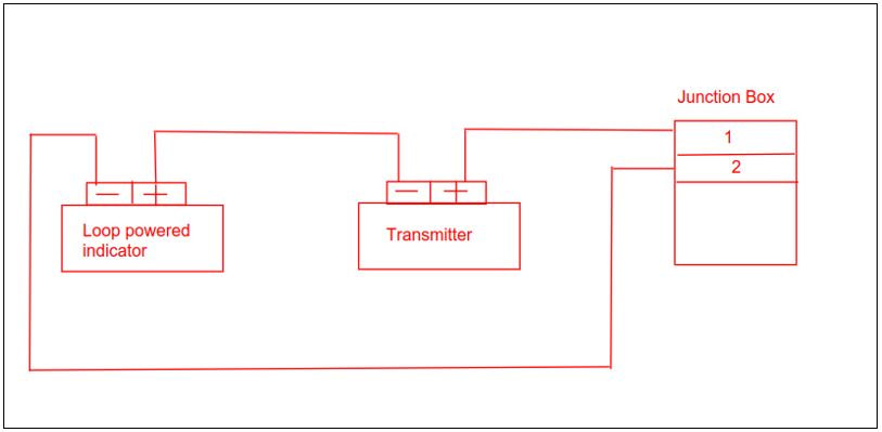
In order to simplify this connection let us refer the regular loop powered connection as shown below.
So Why do we need Loop powered indicator via JB instead of just wiring via transmitter.
Well for a lot of cases the Loop powered indicator and Transmitters are not in close proximity.
A typical situation is when a loop powered indicator is required near the control valve that is controlled via input from transmitter.
The transmitter might not be at the same location as that of control valve.
So instead of wiring all the way from transmitter to Loop powered indicator which would be a single cable running in between them without proper support and systematic route it is prefer by some client to run such cable via JB.
Such that cables are well supported accounted and systematic, prevent tripping of personnel at site.
In order to simplify this connection let us refer the regular loop powered connection as shown below.
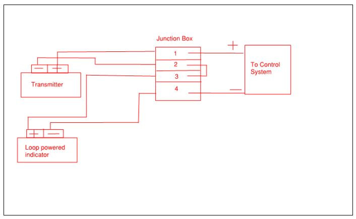
Instead of having the cable running from Transmitter’s -ve terminal to +ve terminal of Loop powered indicator, The -ve cable runs to JB Terminal 2.
The Terminal 2 and 3 of JB are interconnected.
The Terminal 3 of JB then connects to the +ve of loop powered indicator and the -ve terminal of loop powered indicator rums back to JB Terminal 4 completing the Field side connection.
Note the terminals 1 and 4 are sent to Control system side.
Loop powered indicator connection via JB.
Thanks for reading.
Hope its been of value to you.
PS: This is as per best of my current understanding.
Hope its been of value to you.
PS: This is as per best of my current understanding.