Danger Frequency Zones in ASME PTC 19.3TW Standard
Why is frequency limit of 0.8, 0.6 and 0.4 present in ASME PTC 19.3TW standard?
Have you wondered why there are two limits instead of just one resonance frequency?
In my experience very few engineers are actually aware of why ASME recommends this and why WFC cause a plant to be shut for 15 straight years?
As an engineer it is of paramount importance to know this else we would end up in a big catastrophic accident that
happened in Japan (the story is part of the article)
Let us understand this interesting and important concept in simplified and step by step manner.
The Concept of resonance
Let’s take string of a guitar as a system.
Let us excite this string with our hands.
Could you tell me when will we get the highest noise (i.e. Vibration)?
We get the highest vibration when we excite the guitar string in such a way that the frequency of our stimulation matches the resonance frequency of the system in our example the string attached to guitar.
Another example is radio systems, we tune our radio’s electronic components’ frequency to the natural frequency of the FM Chanel and when we exactly sink with it, we get a perfect resonance (i.e. FM station signal).
How does resonance apply to Thermowells?
When an object is kept perpendicular to flow, alternate vortices are formed.
The alternate vortices cause the thermowell to vibrate.
This is called lift force (also known as dynamic force or transverse force)
Resonance occurs when the frequency of vibrations produced due to vortex shedding phenomenon are equal to the Installed natural frequency of the thermowell
The alternate vortices cause the thermowell to vibrate.
This is called lift force (also known as dynamic force or transverse force)
Resonance occurs when the frequency of vibrations produced due to vortex shedding phenomenon are equal to the Installed natural frequency of the thermowell
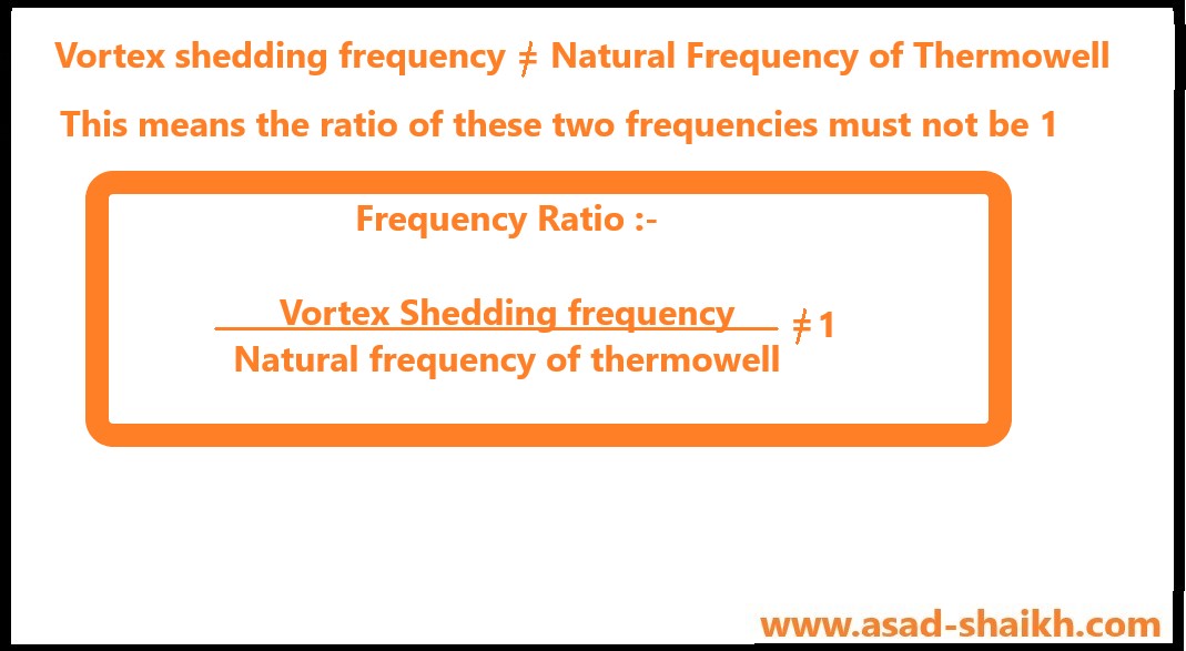
The frequency ratio in thermowell should not be 1
The basic concept is that the frequency of vibrations produced due to vortex shedding phenomenon must not be equal to the natural installed frequency of the thermowell.
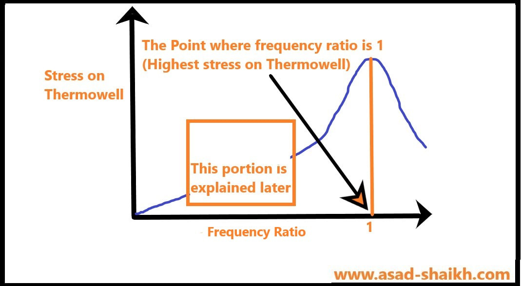
We get the following graph as per above condition
Since during resonance the thermowell will absorb the highest energy have the highest amount of stress leading to its failure (i.e. a broken Thermowell)
Introduction to Danger Zone 1
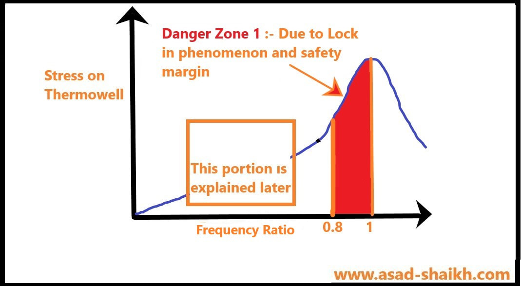
Why does ASME PTC 19.3 TW state that frequency ratio of thermowell must be less than 0.8 rather than 1?
This is because of a concept called safety margin also referred as guard band or lock-in range. Let us call this as “Danger zone 1”
In summary ASME PTC 19.3TW has kept this 20% margin for the following reasons
1. Lock in range- Imagine being near a tornado, what happens if you are even near the tornado, you have high probability to be sucked into it and once you are inside it same like the concept of resonance it is very difficult to get the thermowell out of this destructive vibrations
In simple word, the Thermowell in this range locks-in to the resonance frequency very easily. It takes a considerable change in velocity to get the thermowell out of this region.
2. Safety margin- This band also accounts for loose thermowell manufacturing tolerances, few assumptions made in equations, material property information established to only 3 significant digits, constants used up till 3 or 4 significant digits etc
Introduction to Danger Zone 2
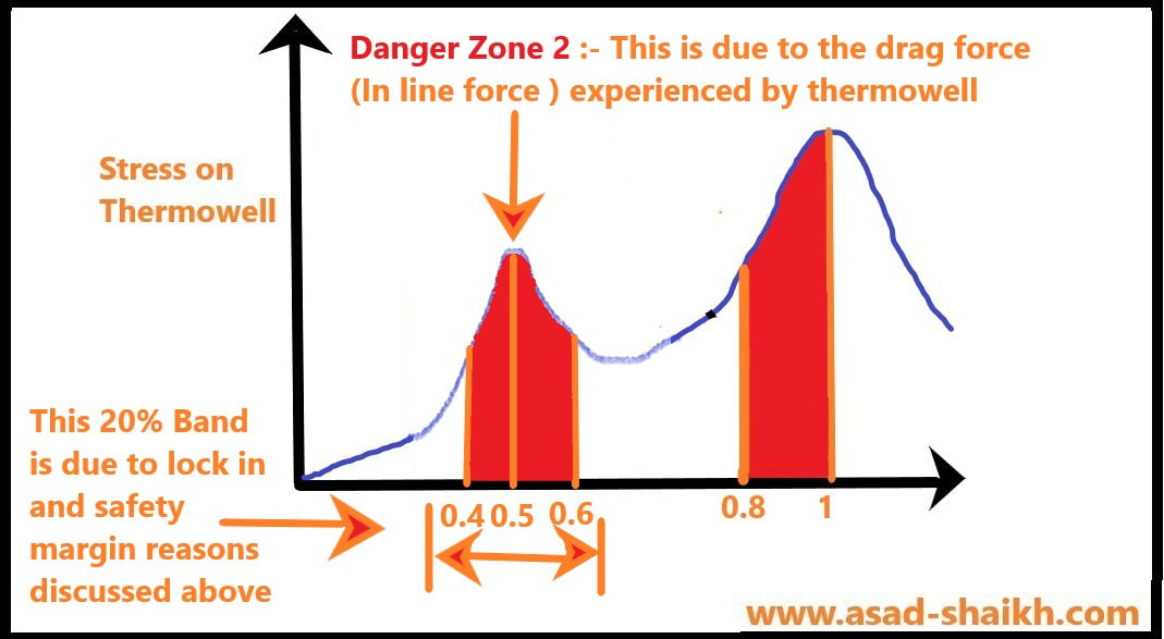
Why does ASME PTC 19.3 TW state that frequency ratio of thermowell must “not” be between 0.4 and 0.6?
A strange thing happened in Monju fast breeder plant in Japan during the year 1995 which cause the plant to be shut down for 15 years.
You might think some major equipment failure might have occurred.
Investigation revealed that a simple thermowell failure cause the sodium coolant to leak out and that led to a catastrophic accident.
The surprising thing was that the failed thermowell had followed ASME PTC 19.3-1974 standard.
So how did this happen?
The old ASME PTC 19.3-1974 had only accounted for lift force (a.k.a Transverse force or dynamic force) that we have discussed above, however there is another force that comes into picture.
This is called Drag force (a.k.a in-line force or static force)
This force is not as destructive as the Lift force (a.k.a Transverse force) as discussed above and hence was not given due consideration in ASME PTC 19.3-1974.
However, if the thermowell is constantly kept in this region of drag force for extended periods of time then it can cause fatigue of thermowell and this is exactly what happened to the thermowell Monju fast breed reactor in Japan.
This alerted the Standards committed and the ASME PTC standard was revised with more stringent condition including the drag force effect.
This phenomenon happens at exact half of the natural frequency of the thermowell.
So, we know resonance occurs when frequency ratio is 1, so this occurs when frequency ratio is 0.5.
Then as discussed above we need to take care of lock-in range and safety tolerance hence a 20% margin is provided and thus we get a limit of 0.4 to 0.6.
The below graph would make this easy to understand
Some Exceptions to the limit of 0.4 to 0.6 and 0.8
What is Scruton Number in Thermowell?
The thermowell have an intrinsic ability to dampen the vibration produced by low density fluid. The factor for mass damping is termed as Scruton Number.
In simple words the higher the “Scruton Number” the high the ability of thermowell to resist vibrations.
In simple words the higher the “Scruton Number” the high the ability of thermowell to resist vibrations.
Case 1: When the Limit of 0.4 to 0.6 is not applicable
This happens when the Scruton Number is greater than 2.5 (i.e. Higher ability to dampen vibration) and the process service has Reynolds number less than 10^5 (More viscous fluid hence vortices created would not be that impactful)
However, the limit of keeping the Frequency ratio below 0.8 is still applicable.
i.e. Danger Zone 2 is not applicable; Just Danger zone 1 must be prevented
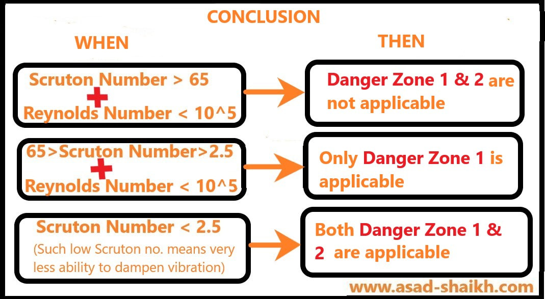
There is also a diagram below that provides a summary of these exceptional cases
However, the limit of keeping the Frequency ratio below 0.8 is still applicable.
i.e. Danger Zone 2 is not applicable; Just Danger zone 1 must be prevented
There is also a diagram below that provides a summary of these exceptional cases
Case 2: When even the limit of frequency ratio below 0.8 is not applicable
When the Scruton Number is greater than 64 (i.e. Very high ability to dampen vibration) and the process service has Reynolds number less than 10^5 (High viscosity fluid thus very less vortices would exist) No Frequency limit must be followed
i.e. Danger Zone 1 and 2 is not applicable
i.e. Danger Zone 1 and 2 is not applicable
Conclusion: -
1) The frequency limit does not apply to thermowell when Scruton Number is greater than 64 and Reynolds number less than 10^5
2) The Limit of have frequency ratio below 0.8 applies when Scruton Number is greater than 2.5 and Reynolds number less than 10^5
3) Both the frequency limits exist when the Scruton Number is lesser than 2.5, since the thermowell is not having a sufficiently high damping to resist the in-line vibrations (i.e. all conditions of frequency limit apply for such cases)
Hope you have found this article helpful.
| PDF download :- Danger_zone_in_asme_ptc_19_3_thermowell_std_rev_1_2021.pdf |
References:
- ASME PTC 19.3 TW 2016
- Emerson White paper 00840-0200-2654, Rev AC
- ASME PTC 19.3 1974
- ABB Presentation on changes in ASME PTC 19.3 1974
Is this Free E-book really important?
We as engineers have tremendous responsibility when it comes to engineering safety and being well grounded in the fundamental concepts of engineering.
Did you know about the concept of erosion affecting our instrument and material selection.
Have a look at the video below of what happened in Husky refinery just because this simple concept of erosion was ignored.
The below E-book covers all these concepts of Erosion, Gasket selection, Fill fluid vaporization, gold plating ,full vacuum etc.
I am really humbled and glad that engineers from 150+ companies including the likes of ADNOC, SABIC, DOW chemicals, Bechtel, Fluor, Worley, Technip, Emerson, ABB, Yokogawa etc have found it valuable and interesting.
I hope you would find the E-book valuable and interesting.
I hope that this book adds value to your knowledge base and engineering acumen.
